
On board Fast Raiding Interception and Special forces Craft (FRISC), vertical accelerations up to about 15 g can occur. To put this into perspective: pilots of fighter jets are exposed to accelerations of up to about 9 g. Being able to predict such forces can help tackle this issue and improve ship designs.
Non-displacement high-speed craft need high speed to reach their objectives, such as for search and rescue or certain military operations. An important limitation of the cruising speed of these ships are the vertical accelerations the crew experiences when sailing in waves.
Axe bow and control system
There are several ways to reduce the vertical accelerations of high-speed craft. One is to improve the design of the ship for better motion behaviour in a seaway, such as the axe bow concept, developed at Delft University of Technology in cooperation with Damen Shipyards. Extending the bow below the keel level of the vessel reduces the number of occasions of the bow coming out of the water and slamming back into it. These slamming events cause large vertical accelerations.
Another characteristic of the axe bow concept is that this bow has almost vertical sides. The forebody is shaped like a sharp wedge. It is not difficult to imagine for anyone with some experience on the diving board that such a sharp wedge causes lower slamming forces than a blunt one.
An example of the axe bow: Damen launches its latest addition to the Fast Crew Supplier range
The crew can also reduce vertical accelerations in a seaway by reducing ship speed. Of course, the throttle can be operated by hand, but this process can also be automated by means of a control system that is optimised for taking the ship to its destination as fast as possible within the limits of vertical accelerations being safe and acceptable for the people on board.
Such a control strategy has been the subject of a line of research at Delft University, involving among others Dr Lex Keuning, Dr Alex van Deyzen and Dr Albert Rijkens. Their PhD theses can be found here and a number of articles were published in the journal ISP (International Shipbuilding Progress).
FASTSHIP
In the research of Keuning, Van Deyzen and Rijkens, the computational model FASTSHIP was used, together with model experiments. FASTSHIP is based on the dynamics of falling wedges in water. In the model, every cross section of the ship is modelled as a falling wedge with a known behaviour of the force in time starting from an initial falling velocity.
Fastship is a semi-emperical method for slamming based on the dynamics of falling wedges
Using linearised potential flow theory for waves combined with the instantaneous vertical velocity of the ship now as a model for the falling velocity, allows us to determine the force on a section of the ship in waves. Integrating these forces over all sections along the length of the vessel gives the force input for solving a coupled set of equations of motion for the ship in a seaway.
An important assumption in FASTSHIP is that there is no hydrodynamic interaction between sections. And wave forces are not the only forces on the vessel. The ship is afloat and at forward speed the buoyancy force needs to be corrected for the changed pressure distribution over the hull. The correction can only be accounted for in an approximate way.
Forward speed also induces a total lift force on the ship that has to be determined from the geometrical information of the individual sections, again in an approximate way. Regression lines for how to account for the approximations were determined from experiments. They depend in part on the range of velocities investigated and on the specific shape of the hull. Their predictive value depends on how well the hull under consideration fits within the shape variations that were considered in the experiments.
Predicting the acceleration level
Experiments are our best way to model the behaviour of fast non-displacement vessels in a seaway. FASTSHIP, until now, was one of the few simulation methods that was able to resemble the accelerations in the experiment with a fair level accuracy, provided that the aforementioned approximations were suitable for the vessel at hand.
Recently, work started to evaluate the 3D numerical method ComFLOW for predicting the acceleration level of a fast non-displacement vessels in irregular waves. Experiments for a Rigid Inflatable Boat (RIB) were designed and performed specifically for that purpose in the towing tank of Delft University of Technology.
ComFLOW features no other approximations than the grid size and requires no calibration
ComFLOW is based on the Navier-Stokes equation with a formulation for displacing the free surface; there are no other approximations behind ComFLOW than the validity of the Navier-Stokes equations and the finite size of the grid distances. In other words, the grid distances need to be small enough to be representative for the physical phenomena being simulated, which makes the computational effort of performing a simulation typically large.
Now, for the first time, we have been successful in simulating the instantaneous pressure level with a method such as ComFLOW with less difference to the experimental levels than FASTSHIP. With this result, ComFLOW has been added to the set of tools that can be used to evaluate fast non-displacement vessel designs for their performance in waves and improve future designs. The remainder of this article is devoted to telling how we arrived at this achievement.
Predicting sloshing, green water and breaking waves
ComFLOW is not a new method. The 3D development started in 1995 under supervision of Prof. Arthur Veldman of the University of Groningen. The first application was predicting the motion behaviour of a satellite under influence of the liquid sloshing in its fuel tank. Sloshing in a situation of effective weightlessness is demanding on the accuracy of the numerical fluid displacement algorithm.
The first application was predicting the motion behaviour of a satellite under influence of the liquid sloshing in its fuel tank
At MARIN, Prof. René Huijsmans and Dr Bas Buchner acknowledged that such an accurate algorithm could have great potential in simulating extreme situations offshore, in which the free surface undergoes large deformations. Examples of these situations are green water on the deck of FPSOs (Floating Production Storage and Offloading vessels), breaking waves against wind turbine support structures or liquid sloshing (now with gravity) in storage tanks of LNG carriers.
More accurate simulations
In multiple joint industry projects, subsidised by the Dutch organisation for the advancement of science (NWO now, STW at the time), several PhD candidates performed research and implemented the developments in the software to perform increasingly more accurate simulations. The PhD candidates were employed by the University of Groningen and, starting in 2005, at Delft University of Technology under supervision of Prof. Jo Pinkster.
Some of these developments accomplished a more complete description of the reality, such as how to deal with irregular long-crested and short-crested waves at the boundaries of computational domains, or how to represent the cushioning effect of compressible air on wave impacts on structures with vertical side walls.
Reducing the number of iterations
Other developments focused on the numerical algorithm and made it faster by a more flexible allocation of dense regions of computational cells only where the action takes place and much less dense regions of cells where nothing much happens. A particularly important reduction of the computational effort has been obtained by improving the algorithm that solves the equations of motion of the fluid, somewhat separate, but still together with the equations of motion of the floating objects in the fluid.
The standard algorithm required a rather large number of iterations, sometimes hundreds, to exchange information between fluid and structure. Now, with a smarter way of exchanging information, the algorithm requires only two iterations.
Developments in ComFLOW are still ongoing. Veldman and Roel Verstappen at the University of Groningen are investigating how turbulent stresses between water and air affect the pressure distribution in wave impacts. Joop Helder and Peter van der Plas at MARIN have invested greatly in streamlining the computer code and have organised a user group where companies using ComFLOW exchange information and support new research and developments.
With a smarter way of exchanging information, the algorithm requires only two iterations.
And the author of this article supervises research of how the effect of a mean current on waves can be accounted for at the boundaries of the computational domain. This latter development inspired the present work on the vertical accelerations of the RIB.
RIB in waves
Every moored object at sea experiences loads not only from waves, but also from mean flows such as wind-driven currents and tides. Waves in ComFLOW could already be simulated as in the experiment for quite some time, but it was important to add the effect of currents so that a next step towards the complete representation of structures out at sea could be taken.
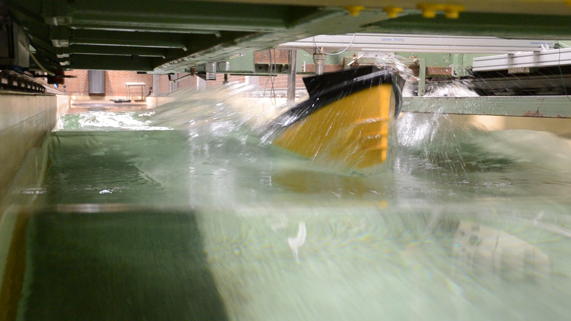
At a certain stage, it was realised that the feature of waves in combination with a mean flow in could be used to emulate a ship at forward speed. ComFLOW excels at simulating wave impacts, and for that reason a measurement campaign in the Delft University towing tank was started with a RIB experiencing slamming in irregular waves.
A spectrum of irregular waves is thought to consist of the sum of individual wave components, each with their own properties. In a towing tank, it is a challenge to be certain about whether wave components in a sea state propagate in one direction or the other. The main objective is that the spectrum is saturated with all desired wave components at their desired amplitude at any position of the RIB as it passes through the tank.
But before the shorter, slower components have reached the RIB, the longer, faster components have already reached the wave-spending beach at the other side of the tank and have reflected with a rather large reflection coefficient because beaches typically do not tend to be very good at dissipating long wave components. This is a common experimental modelling error, but highly undesirable if you are trying to collect validation data that will be compared with results of numerical simulations in which a wave-spending beach is not explicitly modelled.
This is a common experimental modelling error, but highly undesirable if you are trying to collect validation data
It was a puzzle, but by introducing the slower wave components first at the position of the wave board and carefully timing when to start adding the faster components one after the other, it was possible for the RIB to experience the full spectrum, without the disturbance caused by reflected, following waves.
Another important feature of this measurement campaign was that every test should contain at least one slamming event. The chance of slamming is large when the RIB, having arrived at its desired cruising velocity, encounters the highest, steepest wave of the run somewhere in the middle of the tank. This latter demand added to the complexity of controlling the wave board, but it was implemented with success.
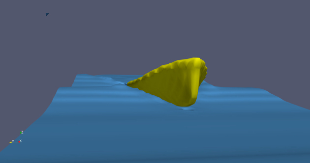
ComFLOW modelling.
Validation study
With the measurement data of the RIB’s positions and accelerations, and the surface elevation of the waves some distance in front of the vessel, a validation study of ComFLOW for the RIB in waves was started. The primary goal of the study was to compare the acceleration level of the RIB as it was modelled in ComFLOW, to the accelerations measured with the accelerometers on the ship model in the tank.
One challenge here was to translate the measured free surface positions in the tank to signals of surface elevation and fluid velocities along the entire incoming wave boundary of the computational domain. A transform of the ship-fixed axis system to an earthfixed axis system and back was required to determine the necessary combination of wave frequencies and wave lengths to use linear potential wave theory for assembling signals of fluid velocities (for the initiated: this introduces a linearisation error that we cannot seem to avoid).
Another challenge was to obtain the accelerations from the simulation results. The acceleration in the equations behind ComFLOW is represented in a discrete way, that is, as the difference between velocities at consecutive time levels divided by the time in between time levels. That means that velocities are known to the algorithm and can be directed to output, but not accelerations. This, combined with the fact that ComFLOW adjusts the difference between time levels dynamically depending on how violent the flow is (smaller time steps for more violent flow), makes that the acceleration reconstructed from the velocities in ComFLOW was rather noisy.
It required a two-sided, high-order Butterworth filter of the velocities to determine the accelerations in such a way that artificial, numerical acceleration peaks were avoided. After comparing the accelerations from the simulations to the ones from the experiment, it was found that there was a very good match between the two.
It required a two-sided, high-order Butterworth filter of the velocities to determine the accelerations in such a way that artificial, numerical acceleration peaks were avoided
A scientific article about the procedure described above and our findings was composed and submitted to the journal International Shipbuilding Progress (ISP), that readers of SWZ|Maritime may have encountered before. Many of that journal’s articles are being published “open access”, opening up its contents and the methods described to the larger maritime community. We have also published data for anyone to download on the 4TU ResearchData repository; a link to the data is provided in the ISP article.
Experiment versus FASTSHIP and ComFLOW
The accelerations of the RIB in the experiment were also compared to FASTSHIP simulation results for the same runs. The comparison between FASTSHIP and the experiment was good, but the comparison between ComFLOW and the experiment was better. Our interpretation is that the forward ship velocities in the experiment were somewhat too low to fit within the limits for which the approximations in FASTSHIP are at their optimum.
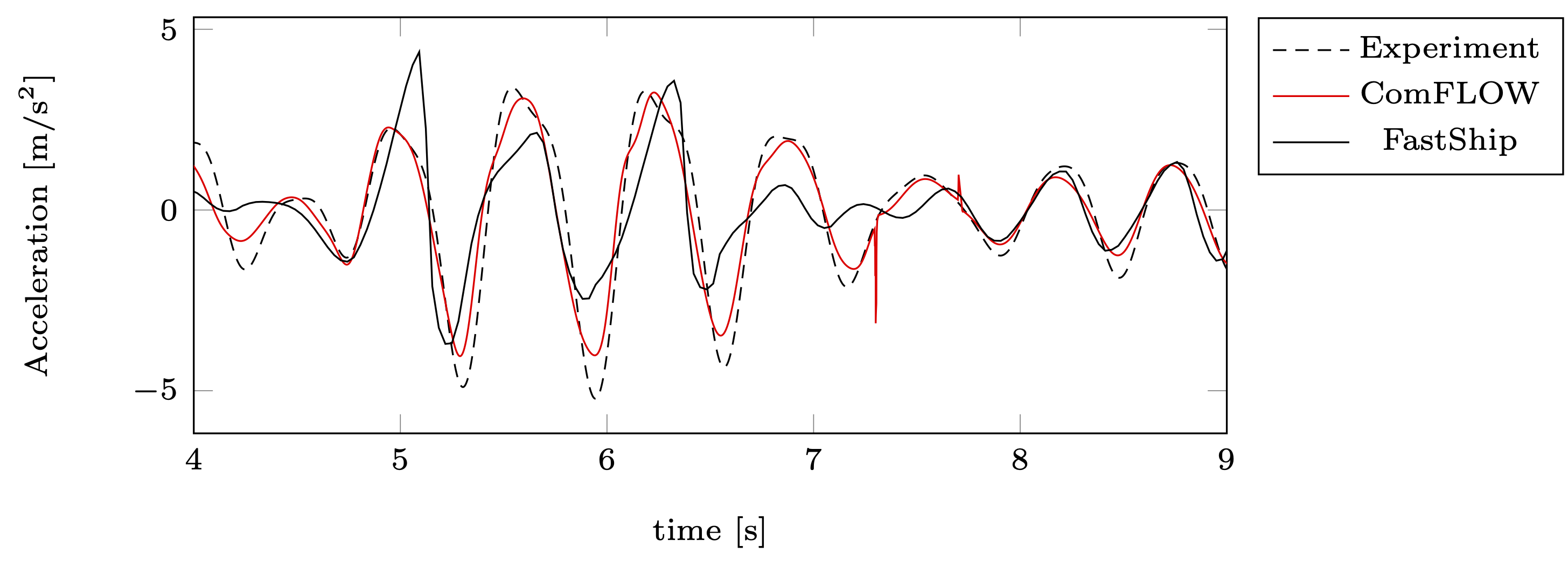
Comparing FASTSHIP and ComFLOW accelerations with the actual experiment.
On the other hand, the FASTSHIP simulations required only a couple of seconds to compute on a single-core of a laptop, whereas the ComFLOW runs took at least two hours on a dedicated twenty-core workstation to complete. FASTSHIP therefore remains important for rapid assessment of and faster-than-real-time applications with high-speed non-displacement craft.
But now we have demonstrated that ComFLOW is a suitable complement to the high-speed toolbox that features no other approximations than the size of the grid and requires no calibration. ComFLOW can be used to optimise hull designs for ship motions in a seaway, and it can potentially also be used to make methods like FASTSHIP more accurate. Both can be extremely valuable.
 This article was written by Dr Ir Peter Wellens and was published in SWZ|Maritime’s April 2021 issue.
Picture (top): A measurement campaign in the Delft University towing tank was started with a RIB experiencing slamming in irregular waves.