
Rolling in waves seems to underlie many of the incidents that involve a loss of containers at sea. This raises the question if container ships are particularly vulnerable in this respect and if there are clear remedies. Could the role of bilge keels for example have been overlooked?
 To develop an opinion on this matter, the present article reviews the current understanding of the factors that underlie the rolling of this ship type. This article was written by Ir Reint P. Dallinga, retired MARIN seakeeping specialist. A shorter version of this article was published in SWZ|Maritime’s May 2021 issue.
Rolling
Regarding the “rolling” of container ships, three types of behaviour come to mind. The first is the “first-order resonant roll” that occurs when the frequency of wave encounter is in-tune with the natural frequency of roll. A second type is referred to as “parametric rolling”, driven by the way rolling itself changes the wave induced excitation and introduces a coupling with the vertical motions.
As explained in the 2014 July/August edition of SWZ [1] it may occur in case of a tuning of the parametric excitation with twice the natural frequency of roll. The third type that yields large heel angles relates to the temporary loss of stability in following waves. Because it occurs only in loading conditions with a very low transverse stability the loss of stability is not considered in the present analysis.
First-order roll excitation
Figure 1 characterises the wave induced roll excitation experienced by and the related roll response of the KCS [2] container ship design sailing in regular waves. The results were obtained with the most complete potential flow method that is currently available, the MARIN Rankine source code FATIMA [3]. Both are given as a function of the wave frequency and the heading of the ship. The figure shows that the roll response is determined by the local excitation in the narrow range with resonant conditions. The peak in longer waves (area A, at lower frequencies) is representative for swell conditions. The higher peak in shorter waves (area B) from the stern quarter is representative for common wind driven seas.
In the above-mentioned swell conditions from more or less transverse directions the bandwidth of the roll response is smaller than the width of a typical wave (induced excitation) spectrum. The fact that only part of the excitation spectrum induces a resonant response means that the peak-response in irregular waves is lower than the peak response in regular waves. In wind waves from the stern quarter (Area B) the relatively constant value of the encounter frequency in the resonant range means that a larger part of the excitation spectrum excites the resonant roll. This means that, irrespective of the underlying excitation, the nature of the tuning yields a higher roll response in these conditions.
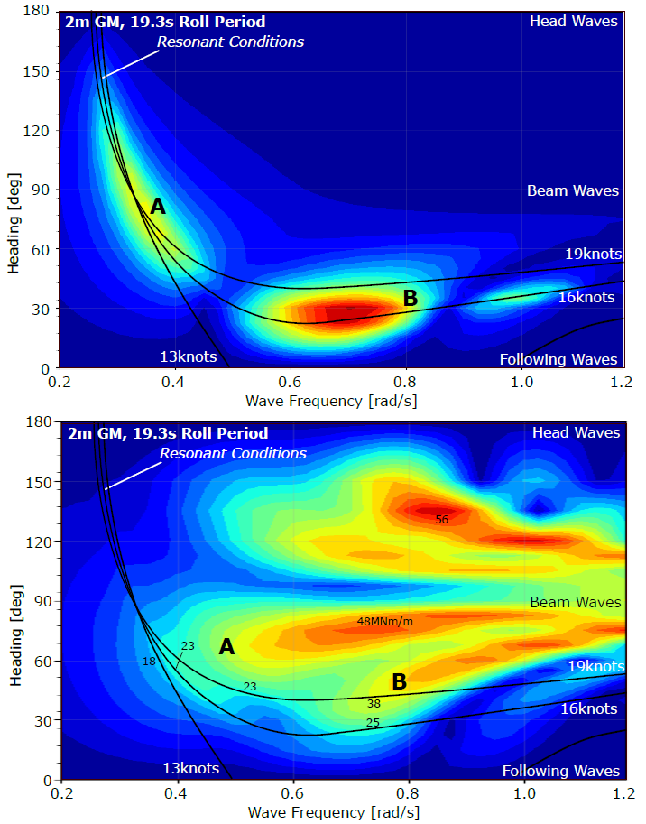
Figure 1. Response Functions of the Wave induced Roll Response (top, deg/m) and Excitation (bottom, kNm/m).
The roll and roll excitation (the roll moment around the centre of gravity (CoG) experienced by the restrained hull in waves) were calculated for 2m GM transverse stability (yielding a natural period of roll of 19.3s) and 16knots speed.
The “humps and hollows” in the excitation are the result of a delicate interplay of local vertical and transverse forces which vary in amplitude and phase along the length of the hull.
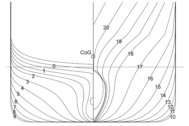
Figure 2. Body Plan KCS (10.8m draught, KG=12.98m).
Varying the speed and the height of the CoG shows that these have a relatively small effect on the global picture of the excitation levels. However, they do affect the local excitation in the resonant range through their effect on the position of the resonant range, which changes with the natural frequency of roll and the wave encounter frequency. In area B, the upward move of this range with a higher GM and a higher speed (and a lower transverse radius of gyration) increases the local excitation significantly.
Effect of hull form
Compared to the excitation experienced by full block hull forms with a cruiser stern, the KCS experiences a high excitation in short waves from the stern quarter (Area B). An analysis of the distribution of the excitation along the length (see figure 3) reveals the reason for this result. It shows a rather large contribution of Sections 3 and 4 in the aft body (see figure 2).It appears that the waterline width in the aft body, which is typical for container ships because it enables them to carry many containers on deck, causes a relatively high roll excitation in the resonant range.dr
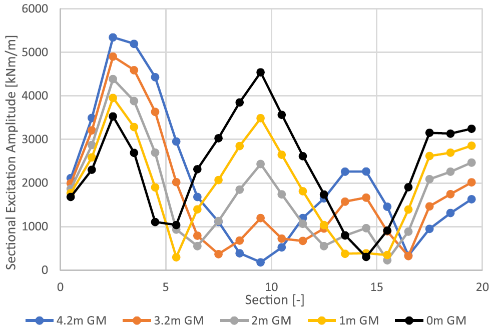
Figure 3. Amplitude of Sectional Contribution to the Roll Excitation, Fn172, 0.7rad/s, 30deg, 10.8m draught.
Parametric excitation
A common procedure to evaluate the “auto-parametric” excitation limits itself to the evaluation of the undisturbed wave induced (“Froude-Krilov”) pressures over the instantaneous wetted surface of the (inclined) hull in motion. Its strongest feature is that it accounts for non-linear changes in the geometry of the instantaneous immersed volume of the hull in waves (immersion of the flare, emergence of the shallow sections in the aft-body) in the evaluation of the instantaneous excitation. A weak point is that the related wave diffraction as well as the heel induced coupling between the vertical motions and roll is neglected.
Effect of hull form
The above-mentioned shortcomings of the commonly applied evaluation method question the common opinion that the pronounced flare and the shallow stern sections drive the parametric excitation of container ships. Real insight awaits careful CFD calculations or measurements on the parametric excitation in waves (instead of the parametric roll response).
Nature of the roll damping
Apart from the excitation, the magnitude of the roll response in the resonant range is governed by the damping in this mode. As a consequence, this quantity is an important characteristic of a given hull design.
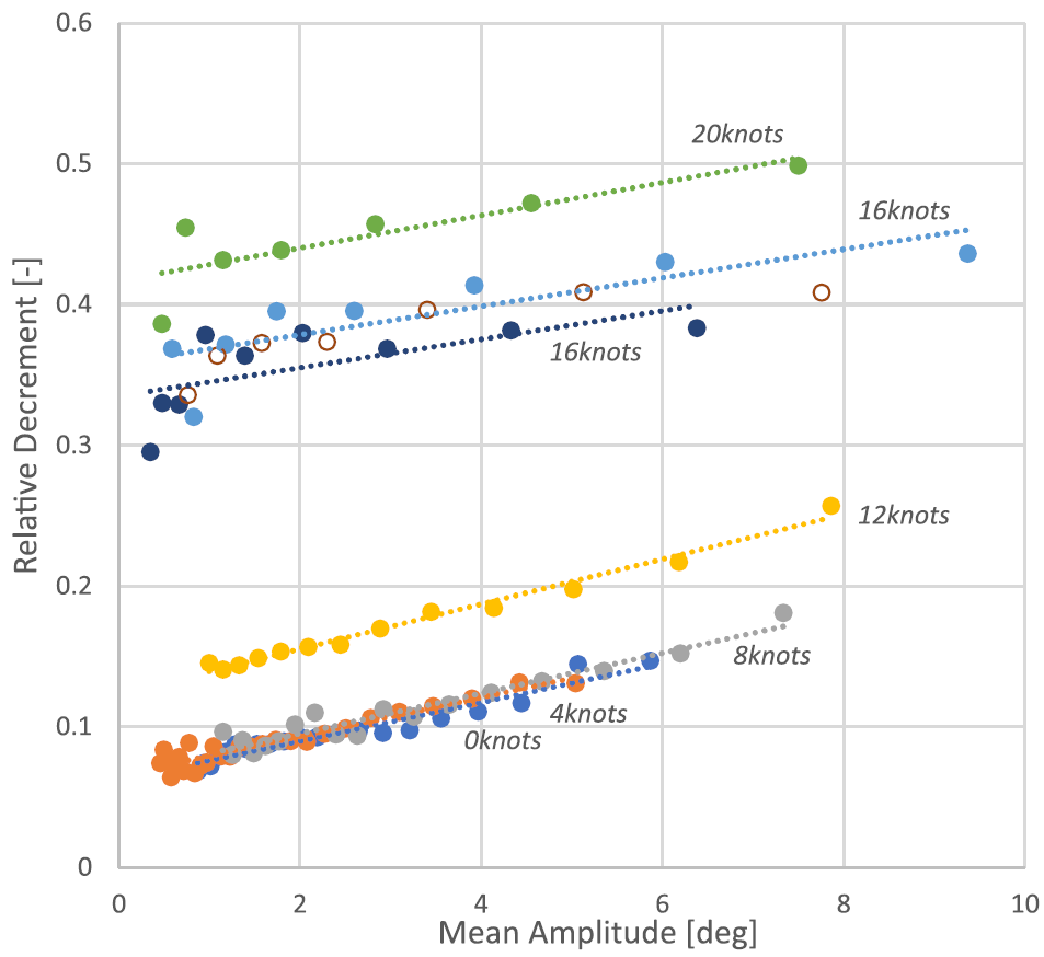
Figure 4. Relative decrement of the roll amplitude during roll decay tests (2m GM, 70cm bilge keels).
Because it is a measure for the dissipated energy in a decaying roll motion, the relative decrease of subsequent amplitudes is a measure for the roll damping. Figure 4 shows the characteristics of the KCS hull; they are quite typical for container ships. The relative decrement consists of a “linear” component that is independent of the roll amplitude (the “intercept” p) and a “quadratic” component that increases with roll amplitude (the “slope” q). The fact that the increase is largely proportional to the roll amplitude suggests that it is caused by quadratic drag forces.
Linear damping components
A numerical reconstruction of the KCS results shows that the measured values can be understood as the sum of a wave making and a lift damping. The first relates to the energy dissipated by the roll induced waves. The second to the deflection of the steady flow by the pitch and yaw motions and the local vertical and transverse velocities at “sharp” trailing edges of the hull.
The wave making damping was computed with the aforementioned Rankine source technique. That fact that it predicts a much higher value than conventional 3D panel methods or strip theory seems to relate to the correct modelling of the effect of forward speed on the dispersion of the roll induced wave system.
In strip theory [4] the lift damping is accounted for by means of so-called “end terms” in the sway, roll and yaw motions. This component was estimated from the 2D added mass derived from the FATIMA estimate of the 3D pressure distribution. The results showed that the lift forces act in two ways: directly through a contribution in the roll damping and indirectly through changes in the sway-roll-coupling.
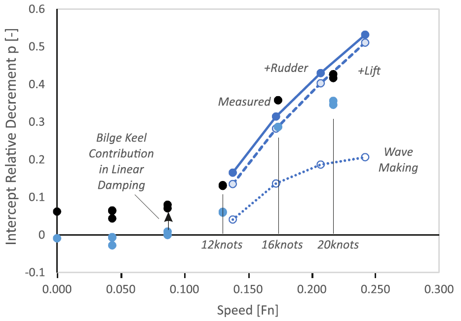
Figure 5. Linear component of the relative decrement, KCS, 2m GM.
In relation to the above it is relevant to mention that the fact that the quadratic damping is relatively high at small roll amplitudes raises the intercept of the relative decrement in this range (and the related apparent linear damping). See figures 4 and 5.
In addition to the above mentioned two terms three additional ones are worth mentioning. The first is the rudder, which was evaluated as an additional end term. The second is the propeller, which proved to be quite small. The third is an often-overlooked effect of the amplitude dependency of the quadratic drag forces in the bilge area; the fact that the quadratic damping is relatively high at small roll amplitudes raises the intercept of the relative decrement and the related apparent linear damping. See figures 4 and 5.
Effect hull form
Two important features of the linear roll damping component are the very low damping at low speed and the rather high value at normal transit speeds.
Because the lift damping is proportional to speed, the low value at low speed is caused by the low wave making component. This is related directly to the long natural period of roll which is typical for container ships.
At transit speed, the distribution of the wave making damping over the length of the hull indicates a significant contribution of the aft-body. The estimated lift damping, which is based on the 2D added mass in the aft body, shows that at moderate speeds most of it originates in the hull just ahead of the propeller. See figure 6. At higher speeds the increased immersion of the stern becomes more important. Taken together, it seems that the relatively wide aft-body of container ships yields a relatively high linear roll damping component at a normal transit speed.
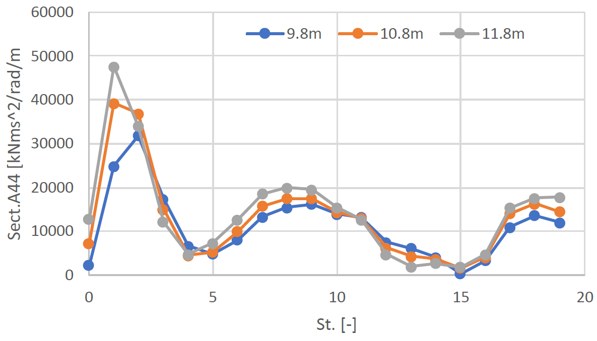
Figure 6. Sectional 2D Added Mass, KCS, Fn172.
Quadratic damping
The numerical reconstruction of the quadratic damping component recognizes two components. The first is the damping induced by the quadratic drag forces experienced by the bilge keels in the roll-induced cross-flow across the bilges. The second, a “carry-over”, is the damping induced by the flow separation vortex acting on the hull above and below the bilge keels.
Bilge keel drag
Regarding the first component the work of van ‘t Veer et.al [5] on FPSOs showed that the bilge keel drag forces can be predicted adequately with a potential flow method. This is achieved with an estimate of the local cross-flow velocity and a drag coefficient that accounts for the amplitude of the cross-flow displacement. In the well-known method of Ikeda et.al;. this estimate is:

In the above the factor r.f.Φa, the product of the arm r from the bilge keel to the CoG, the cross-flow magnification f as a result of the fact that the hull is not “round” and the roll amplitude Φa represents the amplitude of the cross flow across the bilge. With ρ for the density of seawater and bCR for the critical damping, the related slope q of the relative decrement for a bilge keel element with length lBK and height hBK becomes:

The result shows that the amplitude dependency in the drag coefficient does not affect the slope of the relative decrement. However, as indicated in figure 5, the relatively large drag coefficient at small roll amplitudes does change the apparent linear damping through the intercept p. It amounts to:

Carry-over
Potential flow methods do not predict the magnitude of the carry-over. A comparison of the computed contribution the bilge keel drag with measured total quadratic damping shows that for container ship hulls the former constitutes roughly half of the total value.
Like observed in figure 4, the apparent effect of forward speed on the total quadratic damping is relatively small.
Effect of hull form
The calculated value of the contribution of the bilge keels drag is proportional to the third power of their distance to the CoG r, to the square of the magnification f of the roll-induced cross-flow velocity and to the natural frequency of roll. A consequence of this relation is that, because of the relatively large bilge radius and absence of a parallel mid-body, container ship hulls yield a small bilge keel drag contribution. Figure 7 shows that, compared to container ship hulls, full block hull forms yield a bilge keel drag damping which can be 4-5 times higher.
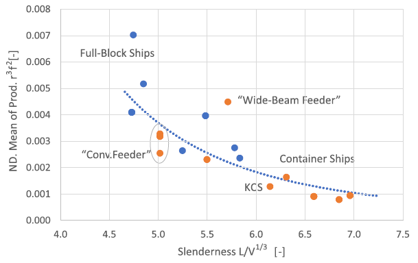
Figure 7. Mean of r3f2/Lpp3 over the length of the bilge keels as a function of the slenderness parameter Lpp/V1/3.
Figure 8 shows the ratio of total quadratic damping over the computed bilge keel contribution for a number of hull forms. It shows that also in terms of the carry-over the full block hulls show a considerably higher damping.
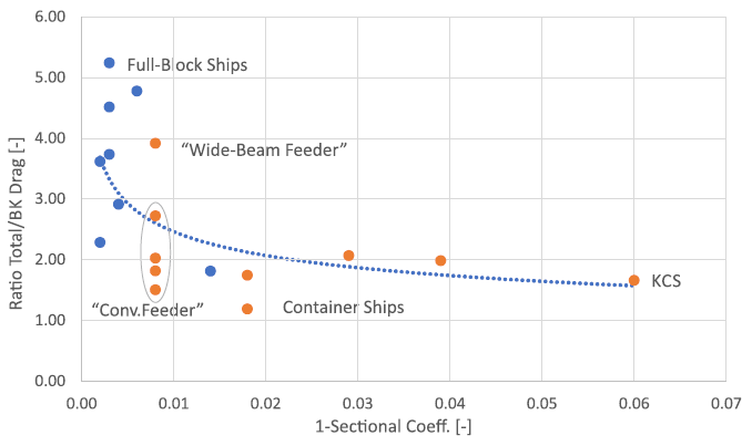
Figure 8. Ratio of measured total (zero-speed) quadratic damping and calculated bilge keel drag contribution as a function of the amidship sectional area coefficient.
False cross-flow velocities
When rolling in waves the local cross-flow velocities on the hull are higher than the isolated roll-induced component. These are induced by the incident and reflected waves and the motion components other than roll, the presence of a drift angle and also course keeping in irregular waves. A well-known consequence is that the bilge keel forces on the weather side are considerably higher than on the leeward side. These “false” cross-flow velocities generally act as a magnifier of the quadratic damping component. As a consequence, the use of the damping in calm water in computing the roll response generally yields an over-estimate of the roll response.
Also read: Video: The forces that caused the MSC Zoe to lose containers explained
First-order resonant roll response
Neglecting the effects of the aforementioned “false” cross-flow velocities on the quadratic damping a tentative estimate of the resonant roll response was made.
A first observation from this analysis is that, as long as they are more or less fully loaded, the roll periods of container ships are such that that resonant rolling hardly occurs in the typical (storm) wave conditions at sea.
In the case of a more unfavourable loading condition with a higher transverse stability (say, 2m GM for the 229m KCS) severe rolling occurs in significant wave heights beyond 3m when encountered from the stern quarter (30deg, Area B in figure 1). Because the linear damping is relatively high at this speed, the impact of the bilge keel height on the tolerable wave height is modest. 70cm bilge keels, which contribute some fifty per cent to the total roll damping at 6.25 deg rms, offer only limited relief.
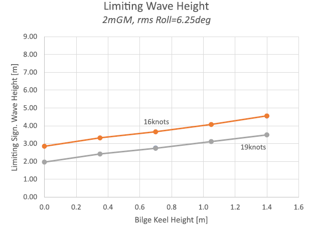
Figure 9. Roll response in resonant irregular wave conditions.
A further increase of the transverse stability up to 3m yields, mainly through the decease in the roll period, an increase of the wave induced excitation in the resonant range. However, because the wave making and the quadratic damping also increase with the higher natural frequency, the impact on the limiting wave height in resonant conditions is not as large as initially expected.
Conclusions
Regarding the question if container ships are particularly vulnerable in terms of the roll response the present analysis seems to confirm this notion. The contribution of the relatively wide waterlines in the aft-body in the wave induced excitation, the low linear damping at low speed caused by the long natural period of roll and the low quadratic damping originating in the slenderness of the hull all seem inherent to the typical choices in the design of these ships.
A favourable characteristic of container ship hulls is the relatively high linear damping at normal transit speeds. However, in loading conditions with a somewhat higher stability this damping is insufficient to compensate for the relatively high excitation.
In unfavourable tuned conditions, the onset of parametric roll is determined by the magnitude of the parametric excitation and the linear roll damping component. The fact that it tends to extremely low values at a reduced speed seems to explain why container ships are also particularly vulnerable in this respect. The low quadratic damping seems to explain the severity of the problem for this ship type.
Recommendation
Because the rolling characteristics relate quite directly to the carrying capacity and fuel efficiency, developing an alternative hull form with improved characteristics seems not straightforward. This makes it all the more important to manage the consequences by adopting quite high bilge keels, devices which may not have gotten the attention they deserve.
Acknowledgements and disclaimer
The author gratefully acknowledges the support of MARIN and the input from its staff in the development of the present analysis. The opinions expressed in this publication are those of the author. They do not purport to reflect the opinions or views of MARIN.
References
- SWZ|Maritime, July/August 2014
- KCS, https://www.w2022.nl/kriso-container-ship-kcs
- Bunnik, T.H.J. 1999. Seakeeping calculations for ships, taking into account the non-linear steady waves, PhD Thesis, Delft University of Technology, the Netherlands
- Vugts, Dr.Ir.J.H., The hydrodynamic Forces and Ship Motions in Oblique Waves, TNO Report No. 150 S, 1971
- Van ‘t Veer et.al., On Roll Hydrodynamics of FPSO’s Fitted with Bilge Keels and Riser Balcony, ASME 2011
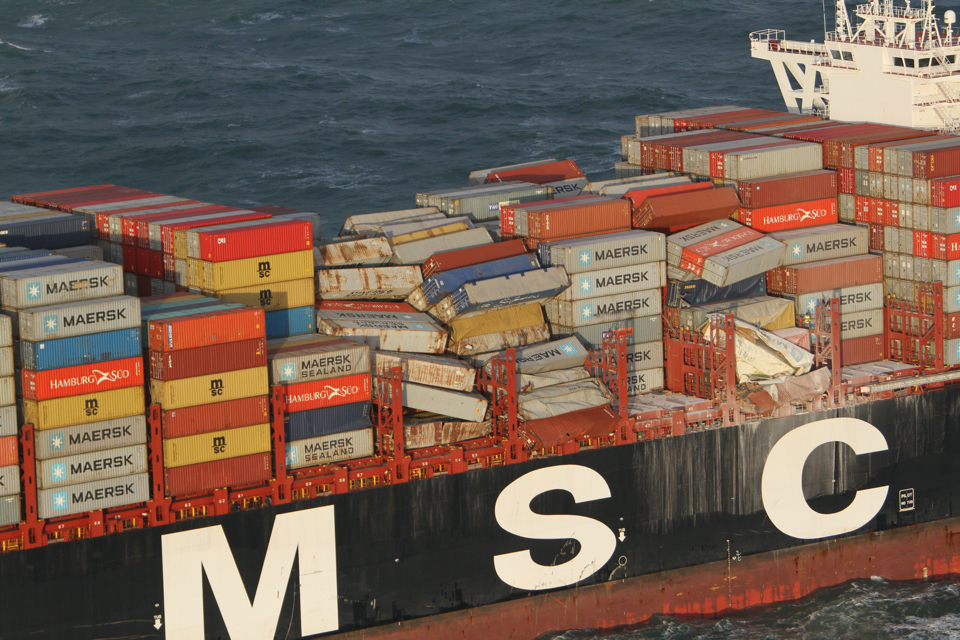
Picture (top): The MSC Zoe lost 342 containers in bad weather in the night of 1 to 2 January 2019, north of the Wadden Islands (picture by the Netherlands Coast Guard).
Also read: Are container ships overloaded?